· by Jason Miller
VXLAN EVPN Multisite Setup – Part 1
Below is the diagram I’ll be working with. For this part, I’ll be setting up site 1 with a simple L2 vxlan allowing PC2 and 3 to communicate.
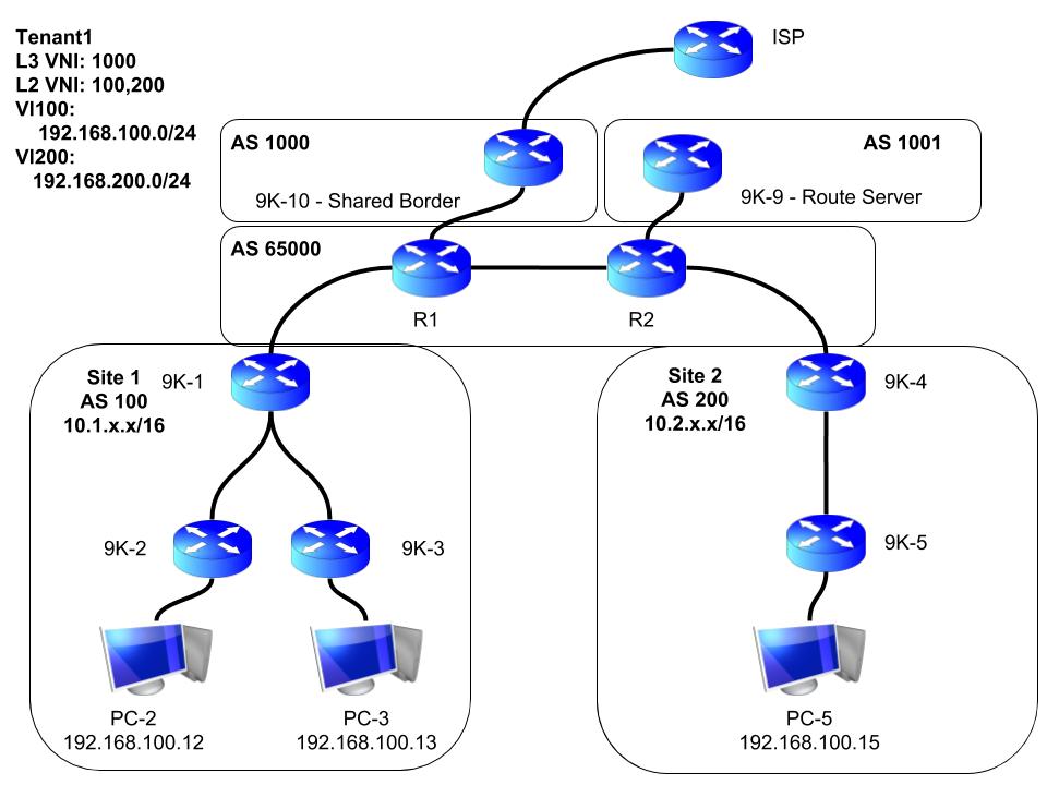
Starting out with all interfaces already configured, but that’s it. Each router will have a loopback0 interface used for the OSPF router-id, as well as bgp source interface. Loopback1 will be used as the VTEP IPs for the leaf nodes 9K-2 and 3. The spine node 9K-1 will eventually use loopback1 for BUM traffic when we start introducing L3 routing. The spine will also have a loopback2 interface to be used for the multisite border gateway interface used later on.
Configuration of the underlay is first
- IGP – OSPF will be used in this case to advertise the loopback0 addresses for BGP later
- PIM – Will be used for BUM traffic
- iBGP – Advertising loopback1 (spine and leafs), and loopback2 (spine only, used later)
Next, i’m going to configure the overlay
- iBGP – Adding the EVPN address family used to advertise the hosts mac addresses
- VXLAN –
- Create the VNI for vlan 100
- Configure route distinguisher, and route targets
- Create the NVE interface
Underlay
Verifying the interfaces are configured already:
9K-1 (Spine) to 9K-2 (Leaf)
9K-1# ping 10.1.12.2
PING 10.1.12.2 (10.1.12.2): 56 data bytes
64 bytes from 10.1.12.2: icmp_seq=0 ttl=254 time=98.446 ms
64 bytes from 10.1.12.2: icmp_seq=1 ttl=254 time=53.609 ms
64 bytes from 10.1.12.2: icmp_seq=2 ttl=254 time=48.822 ms
64 bytes from 10.1.12.2: icmp_seq=3 ttl=254 time=21.514 ms
64 bytes from 10.1.12.2: icmp_seq=4 ttl=254 time=42.98 ms
^C
--- 10.1.12.2 ping statistics ---
5 packets transmitted, 5 packets received, 0.00% packet loss
round-trip min/avg/max = 21.514/53.074/98.446 ms
9K-1 (Spine) to 9K-3 (Leaf)
9K-1# ping 10.1.13.2
PING 10.1.13.2 (10.1.13.2): 56 data bytes
64 bytes from 10.1.13.2: icmp_seq=0 ttl=254 time=41.282 ms
64 bytes from 10.1.13.2: icmp_seq=1 ttl=254 time=38.292 ms
64 bytes from 10.1.13.2: icmp_seq=2 ttl=254 time=59.753 ms
64 bytes from 10.1.13.2: icmp_seq=3 ttl=254 time=30.691 ms
64 bytes from 10.1.13.2: icmp_seq=4 ttl=254 time=117.292 ms
^C
--- 10.1.13.2 ping statistics ---
5 packets transmitted, 5 packets received, 0.00% packet loss
round-trip min/avg/max = 30.691/57.462/117.292 ms
9K-1 to Router 1 (to be used later on)
9K-1# ping 10.0.101.1
PING 10.0.101.1 (10.0.101.1): 56 data bytes
64 bytes from 10.0.101.1: icmp_seq=0 ttl=254 time=14.741 ms
64 bytes from 10.0.101.1: icmp_seq=1 ttl=254 time=21.196 ms
64 bytes from 10.0.101.1: icmp_seq=2 ttl=254 time=22.179 ms
64 bytes from 10.0.101.1: icmp_seq=3 ttl=254 time=13.443 ms
64 bytes from 10.0.101.1: icmp_seq=4 ttl=254 time=33.057 ms
^C
--- 10.0.101.1 ping statistics ---
5 packets transmitted, 5 packets received, 0.00% packet loss
round-trip min/avg/max = 13.443/20.923/33.057 ms
OSPF
Enable OSPF on all 3 nodes
feature ospf9K-1
router ospf 100
 router-id 10.1.255.1
int eth1/1.12
 ip ospf network point-to-point
 ip router ospf 100 area 0
int eth1/1.13
 ip ospf network point-to-point
 ip router ospf 100 area 0
int lo0
 ip router ospf 100 area 0
9K-2
router ospf 100
 router-id 10.1.255.2
int eth1/1.12
 ip ospf network point-to-point
 ip router ospf 100 area 0
int lo0
 ip router ospf 100 area 0
9K-3
router ospf 100
 router-id 10.1.255.3
int eth1/1.13
 ip ospf network point-to-point
 ip router ospf 100 area 0
int lo0
 ip router ospf 100 area 0
Verify
9K-1
9K-1# sh ip ospf nei
 OSPF Process ID 100 VRF default
 Total number of neighbors: 2
 Neighbor ID     Pri State            Up Time  Address         Interface
 10.1.255.2        1 FULL/ -          00:29:54 10.1.12.2       Eth1/1.12
 10.1.255.3        1 FULL/ -          00:00:43 10.1.13.2       Eth1/1.13
Ping loopback0 interfaces of leafs sourced from spine’s loopback0
9K-1# ping 10.1.255.2 source-int lo0
PING 10.1.255.2 (10.1.255.2): 56 data bytes
64 bytes from 10.1.255.2: icmp_seq=0 ttl=254 time=26.672 ms
64 bytes from 10.1.255.2: icmp_seq=1 ttl=254 time=19.184 ms
64 bytes from 10.1.255.2: icmp_seq=2 ttl=254 time=11.639 ms
64 bytes from 10.1.255.2: icmp_seq=3 ttl=254 time=17.462 ms
64 bytes from 10.1.255.2: icmp_seq=4 ttl=254 time=36.023 ms
^C
--- 10.1.255.2 ping statistics ---
5 packets transmitted, 5 packets received, 0.00% packet loss
round-trip min/avg/max = 11.639/22.196/36.023 ms
!
!
9K-1# ping 10.1.255.3 source-int lo0
PING 10.1.255.3 (10.1.255.3): 56 data bytes
64 bytes from 10.1.255.3: icmp_seq=0 ttl=254 time=33.3 ms
64 bytes from 10.1.255.3: icmp_seq=1 ttl=254 time=36.843 ms
64 bytes from 10.1.255.3: icmp_seq=2 ttl=254 time=28.824 ms
64 bytes from 10.1.255.3: icmp_seq=3 ttl=254 time=10.635 ms
64 bytes from 10.1.255.3: icmp_seq=4 ttl=254 time=19.692 ms
^C
--- 10.1.255.3 ping statistics ---
5 packets transmitted, 5 packets received, 0.00% packet loss
PIM
Enable PIM on all 3 nodes
feature pim9K-1
– Loopback0 requires it because this IP will be used as the PIM RP
– Loopback1 requires it because this will be the source IP for BUM traffic later on
– Loopback2 does not require it because it will not be used for BUM traffic
int lo0
 ip pim sparse
int lo1
 ip pim sparse
int eth1/1.12
 ip pim sparse
int eth1/1.13
 ip pim sparse
ip pim rp-add 10.1.255.1
9K-2
int lo1
 ip pim sparse
int eth1/1.12
 ip pim sparse
ip pim rp-add 10.1.255.1
9K-3
int lo1
 ip pim sparse
int eth1/1.13
 ip pim sparse
ip pim rp-add 10.1.255.1
Verify
9K-1
9K-1# sh ip pim nei
PIM Neighbor Status for VRF "default"
Neighbor        Interface            Uptime    Expires   DR       Bidir-  BFD
 ECMP Redirect
                                                         Priority Capable State
    Capable
10.1.12.2       Ethernet1/1.12       00:35:56  00:01:23  1        yes     n/a
  no
10.1.13.2       Ethernet1/1.13       00:07:57  00:01:22  1        yes     n/a
  no
iBGP
Enable BGP on all three
feature bgp9K-1
router bgp 100
 add ipv4 un
  net 10.1.255.1/32
  net 10.1.254.1/32
  net 10.1.253.1/32
 nei 10.1.255.2
  remote-as 100
  update-so lo0
  add ipv4 un
   route-reflector-client
 nei 10.1.255.3
  remote-as 100
  update-so lo0
  add ipv4 un
   route-reflector-client
9K-2
router bgp 100
 add ipv4 un
  net 10.1.254.2/32
 nei 10.1.255.1
  remote-as 100
  update-so lo0
  add ipv4 un
9K-3
router bgp 100
 add ipv4 un
  net 10.1.254.3/32
 nei 10.1.255.1
  remote-as 100
  update-so lo0
  add ipv4 un
Verify
9K-1
9K-1# sh bgp ip un sum
BGP summary information for VRF default, address family IPv4 Unicast
BGP router identifier 10.1.255.1, local AS number 100
BGP table version is 8, IPv4 Unicast config peers 2, capable peers 2
4 network entries and 4 paths using 880 bytes of memory
BGP attribute entries [2/328], BGP AS path entries [0/0]
BGP community entries [0/0], BGP clusterlist entries [0/0]

Neighbor        V    AS MsgRcvd MsgSent   TblVer  InQ OutQ Up/Down  State/PfxRcd
10.1.255.2      4   100      24      22        8    0    0 00:13:34 1
10.1.255.3      4   100      23      22        8    0    0 00:13:29 1
Make sure 9K-1 has the routes for Leaf’s Loopback1 addresses (10.1.254.x)
9K-1# sh ip route bgp
.....
10.1.254.2/32, ubest/mbest: 1/0
    *via 10.1.255.2, [200/0], 00:14:23, bgp-100, internal, tag 100
10.1.254.3/32, ubest/mbest: 1/0
    *via 10.1.255.3, [200/0], 00:14:18, bgp-100, internal, tag 100
OVERLAY
iBGP
Enable EVPN on all three
feature nv overlay
nv overlay evpn
9K-1
router bgp 100
 nei 10.1.255.2
  add l2 ev
   send-comm both
   route-reflector-client
 nei 10.1.255.3
  add l2 ev
   send-comm both
   route-reflector-client
9K-2
router bgp 100
 nei 10.1.255.1
  add l2 ev
   send-comm both
9K-3
router bgp 100
 nei 10.1.255.1
  add l2 ev
   send-comm both
Verify
9K-1
9K-1# sh bgp l2 ev sum
BGP summary information for VRF default, address family L2VPN EVPN
BGP router identifier 10.1.255.1, local AS number 100
BGP table version is 4, L2VPN EVPN config peers 2, capable peers 2
0 network entries and 0 paths using 0 bytes of memory
BGP attribute entries [0/0], BGP AS path entries [0/0]
BGP community entries [0/0], BGP clusterlist entries [0/0]

Neighbor        V    AS MsgRcvd MsgSent   TblVer  InQ OutQ Up/Down  State/PfxRcd
10.1.255.2      4   100      24      22        4    0    0 00:13:40 0
10.1.255.3      4   100      23      22        4    0    0 00:13:34 0
Create VNIs
Required to create the VNIs on both leaf nodes
feature vn-segment9K-2 & 3
Create vlan 100, specify a VNI, and then configure evpn to auto create the RD and route-targets based on the BGP AS number
vlan 100
 vn 100
evpn
 vni 100 l2
  rd auto
  route-target both auto
Create NVI
9K-2 & 3
int nve1
 host-reach protocol bgp
 source-int lo1
 mem vni 100
  mcast 239.1.1.1
  suppress-arp
 no shut
Verify
If all goes well, your NVE interface should be showing as up. If not, double check that your loopback1 interface is up.
9K-2(config-if-nve)# sh nve int
Interface: nve1, State: Up, encapsulation: VXLAN
 VPC Capability: VPC-VIP-Only [not-notified]
 Local Router MAC: 0c1f.d9d8.4d07
 Host Learning Mode: Control-Plane
 Source-Interface: loopback1 (primary: 10.1.254.2, secondary: 0.0.0.0)
!
9K-3(config-if-nve)# sh nve int
Interface: nve1, State: Up, encapsulation: VXLAN
 VPC Capability: VPC-VIP-Only [not-notified]
 Local Router MAC: 0c1f.d99b.2b07
 Host Learning Mode: Control-Plane
 Source-Interface: loopback1 (primary: 10.1.254.3, secondary: 0.0.0.0)
That’s all. Everything should be ready for PC2 and 3 to communicate. I’ll configure their interfaces into vlan 100, and then try to ping between them. PC2 = 192.168.100.12, PC3 = 192.168.100.13
9K-2 & 3
int eth1/3
 switchport
 switchport access vlan 100
 spanning-tree port type edge
Verify
PC-2> ping 192.168.100.13
84 bytes from 192.168.100.13 icmp_seq=1 ttl=64 time=30.543 ms
84 bytes from 192.168.100.13 icmp_seq=2 ttl=64 time=94.319 ms
!
PC-3> ping 192.168.100.12
84 bytes from 192.168.100.12 icmp_seq=1 ttl=64 time=75.988 ms
84 bytes from 192.168.100.12 icmp_seq=2 ttl=64 time=31.889 ms
Now to see what it looks like on the leafs:
Nexus 9000v doesn’t show these MACs in the MAC table, but this command below lets you see what it knows about:
9K-2# sh system internal l2fwder mac
Legend:
        * - primary entry, G - Gateway MAC, (R) - Routed MAC, O - Overlay MAC
        age - seconds since last seen,+ - primary entry using vPC Peer-Link,
        (T) - True, (F) - False, C - ControlPlane MAC
   VLAN     MAC Address      Type      age     Secure NTFY Ports
---------+-----------------+--------+---------+------+----+------------------
*   100    0050.7966.6801   dynamic   00:03:13   F     F     Eth1/3
*   100    0050.7966.6802    static   -          F     F  nve-peer1 10.1.254.3
!
!
9K-2# sh l2route mac-ip all
Flags -(Rmac):Router MAC (Stt):Static (L):Local (R):Remote (V):vPC link
(Dup):Duplicate (Spl):Split (Rcv):Recv(D):Del Pending (S):Stale (C):Clear
(Ps):Peer Sync (Ro):Re-Originated
Topology    Mac Address    Prod   Flags         Seq No     Host IP         Next-Hops
----------- -------------- ------ ---------- --------------- ---------------
100         0050.7966.6801 ARP    L,            0          192.168.100.12 Eth1/3
100         0050.7966.6802 BGP    --            0          192.168.100.13 10.1.254.3
Leaf node 9K-2 has the MAC address for both PC2 and 3 in it’s L2RIB already. You can see that it also knows PC3’s mac is reachable via NVE peer 10.1.254.3, which is 9K-3’s loopback1 IP. We should be able to see 9K-3 as an NVE peer now.
9K-2# sh nve peer
Interface Peer-IP          State LearnType Uptime   Router-Mac
--------- ---------------  ----- --------- -------- -----------------
nve1      10.1.254.3       Up    CP        00:07:09 n/a
!
9K-2# sh nve peer det
Details of nve Peers:
----------------------------------------
Peer-Ip: 10.1.254.3
    NVE Interface       : nve1
    Peer State          : Up
    Peer Uptime         : 00:07:12
    Router-Mac          : n/a
    Peer First VNI      : 100
    Time since Create   : 00:08:51
    Configured VNIs     : 100
    Provision State     : peer-add-complete
    Learnt CP VNIs      : 100
    vni assignment mode : SYMMETRIC
    Peer Location       : N/A
On 9K-1, you should be able to see both PCs in the BGP table. The 0.0.0.0 are just MAC only advertisements, but you can also see the IP being advertised in a separate entry which is because we have enabled ‘suppress-arp’ on the NVE interface.
9K-1# sh bgp l2 ev
......
Network Next Hop Metric LocPrf Weight Path
Route Distinguisher: 10.1.255.2:32867
*>i[2]:[0]:[0]:[48]:[0050.7966.6801]:[0]:[0.0.0.0]/216
10.1.254.2 100 0 i
*>i[2]:[0]:[0]:[48]:[0050.7966.6801]:[32]:[192.168.100.12]/248
10.1.254.2 100 0 i

Route Distinguisher: 10.1.255.3:32867
*>i[2]:[0]:[0]:[48]:[0050.7966.6802]:[0]:[0.0.0.0]/216
10.1.254.3 100 0 i
*>i[2]:[0]:[0]:[48]:[0050.7966.6802]:[32]:[192.168.100.13]/248
10.1.254.3 100 0 i
That’s all for the single site, L2 VXLAN configuration.